The AI That Reads Blueprints Like an Engineer, Not Like a Scanner
Based on: Drawing-Recode: Annotation Grounding for Parametric CAD Code Generation from Raster 2D CAD Drawings — Mingi Kim, Yongjun Kim, Hyungki Kim
Somewhere in a manufacturing plant right now, there's a filing cabinet full of drawings for parts nobody can order anymore. A bracket from 1994, dimensioned by hand, photocopied so many times the lines have gone soft. The company that made the original part is gone. The engineer who drew it retired a decade ago. But a customer still needs that exact bracket, and the only record of it is a flat piece of paper.
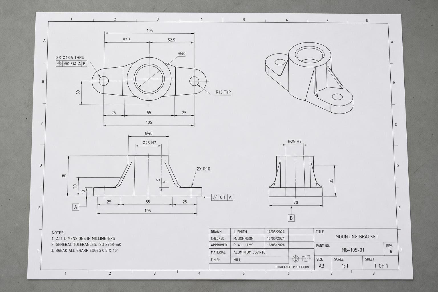
To manufacture that part on a modern CNC machine or 3D printer, someone has to turn the drawing back into a live, parametric 3D model: not a picture of the part, but a set of instructions a computer can resize, edit, and machine. Today that means a CAD technician sitting down and redrawing the whole thing by hand, reading each dimension off the paper and re-entering it into software. It's slow, it's expensive, and it's exactly the kind of task a good AI system should be able to help with.
A new paper called Drawing-Recode, from researchers Mingi Kim, Yongjun Kim, and Hyungki Kim, tries to automate that pipeline: feed in a scanned 2D drawing, get back working CAD code. What makes it interesting isn't just that it attempts this. It's the specific problem the authors identify as the real bottleneck, and it's one that most OCR-adjacent systems quietly ignore.
The gap between reading a number and understanding what it measures
Start with a distinction that matters here: raster versus vector. A vector CAD file (a DXF or a native SolidWorks file, for instance) stores geometry as structured data: this line runs from point A to point B, this circle has this radius. A raster image is just pixels. A scanned drawing, a photo of a blueprint, a PDF that's really a picture underneath, all of these are raster. There's no structure in them at all, just colored dots that happen to look like lines and text to a human eye.
Reading the text off a raster CAD drawing is a solved-ish problem. OCR can pull "Ø25" or "50.5" off a page reasonably well, dimension symbols and all. That's not what Drawing-Recode is really about.
The harder problem is this: once you've read "50.5" off the page, what does it belong to? A CAD drawing isn't a form with labeled fields. It's a picture of a part, with a scatter of dimension lines and numbers pointing at specific edges, holes, and surfaces. A "50.5" near a rectangle probably describes its width, but it might describe the diagonal, or a hole spacing, or something three lines away that the extension line just happens to cross. Get that link wrong and you don't get a slightly-off part. You get a part that's structurally wrong, because a parametric CAD model is a sequence of operations (sketch this rectangle, extrude it this far, cut this hole) where every step depends on the numbers being attached to the right geometry.
The paper's framing is that prior systems either work only on vector drawings (which already have this structure baked in, so there's nothing to solve) or are narrow, built for one kind of drawing or one industry, and none of them explicitly connect an annotation to the geometry it's describing. They treat text recognition and geometry recognition as separate jobs and hope the connection sorts itself out downstream. It usually doesn't.
How Drawing-Recode ties a number to the line it measures
The architecture has a few distinct pieces, and the interesting one is in the middle.
First, an image encoder looks at the raster drawing and extracts geometric features: essentially, a rich internal representation of the lines, curves, and shapes on the page, independent of any text. Separately, a text recognition module reads the annotations: the dimension numbers, tolerances, and labels scattered across the drawing. So far this is standard document AI, two specialized readers working in parallel.
The actual contribution is what happens next. Drawing-Recode uses cross-attention, a mechanism that lets one set of features "look at" another set and decide what's relevant, to connect each recognized annotation back to the specific geometric features it's describing. Think of it as the model learning to draw its own extension lines: given the text "50.5," it learns to search the geometric representation for the edge that number most plausibly measures, the same way a human eye follows a dimension line from the number back to the part outline.
To make that connection reliable rather than approximate, the authors add something they call Annotation Grounding Loss (AGL). A "loss" in machine learning is just the penalty the model gets during training when its output is wrong, the signal it uses to improve. A normal training setup might only penalize the model for getting the final CAD code wrong. AGL adds an extra, explicit penalty for getting the annotation-to-geometry link wrong, even before you get to the final output. That's a deliberate design choice: rather than hoping the right grounding emerges as a side effect of good code generation, they train the model to get the grounding right on its own terms.
Once the geometry, the recognized text, and the grounded links between them are combined into one feature set, that gets fed into a large language model (LLM), the same family of model behind tools like ChatGPT, adapted here to generate code instead of prose. The output isn't a picture or a set of coordinates. It's CAD code in what the authors call Structured Parametric CAD Code (SPCC) format: a sequence of operations like "sketch this profile, extrude it 12mm, cut a 6mm hole here" that a CAD program can execute to rebuild the actual 3D model, fully editable, not just a static shape.
What they found, and the part that actually matters for real-world use
The paper reports that Drawing-Recode outperforms existing baseline methods at recovering correct parametric CAD sequences from raster drawings. That's expected. Any new method in a paper needs to beat what came before it, or there's no paper.
The more telling result is the second claim: the system stays robust on scanned drawings that resemble real industrial conditions. This is worth sitting with, because it's the difference between a demo and a tool. Clean, high-resolution CAD renderings are the easy case. Real-world drawings, the kind sitting in that filing cabinet, are photocopies of photocopies, faded, slightly rotated, with coffee rings and pencil marks the AI has to route around. A system that only performs well on pristine inputs is solving a problem nobody actually has. The authors specifically designed for and tested against degraded scans, which suggests they understood that the lab-clean case was never the point.
That said, the abstract doesn't hand over the hard numbers, accuracy percentages, exact baseline comparisons, dataset sizes, so treat "outperforms" and "remains robust" as directional claims backed by experiments rather than a scoreboard you can cite directly. If you're deciding whether to build on this, the mechanism (explicit grounding via cross-attention and a dedicated loss) is the transferable idea, more so than any specific benchmark number in this early paper.
Why it matters for anyone building or choosing OCR
Zoom out from CAD specifically and there's a lesson here for document AI generally, which is squarely OpenOCR's territory.
A huge amount of real-world document processing isn't "read the text." It's "figure out which text belongs to which thing." An invoice line item needs to link to the right SKU and the right total. A medical form's checkbox needs to link to the label next to it, not the label three rows up. A financial statement's footnote marker needs to link to the number it annotates. In every one of these cases, plain OCR gets you the characters and completely fails to get you the relationship. That relationship is usually where the actual value is.
Drawing-Recode is a clean case study in solving that relationship problem on purpose, instead of hoping a big enough model learns it by accident. The explicit design choice, a dedicated loss function just for grounding, cross-attention that's architecturally forced to connect the two modalities, is the part worth remembering even if you never touch a CAD drawing. When you're evaluating an OCR or document-AI engine for a task that involves annotations, labels, or cross-references (not just running text), ask the vendor whether their system explicitly models those links or just extracts text and geometry separately and leaves you to stitch them together. The gap between those two approaches is usually where accuracy problems live.
For OpenOCR users specifically, this also points at a category worth watching: engines built for a narrow but deep task, like part digitization, tend to beat general-purpose OCR on that task even when the general-purpose engine has a bigger training budget behind it. If you're digitizing engineering archives, the right move probably isn't running a generic OCR engine and writing custom glue code to guess which numbers belong to which lines. It's finding or building something closer to Drawing-Recode's approach, where the linking is part of the model, not an afterthought bolted on in post-processing.
Where this still falls short
A few gaps stand out, some acknowledged by the framing of the paper, others just inherent to the approach as described.
The scope is 2D drawings producing 3D parametric sequences for individual parts, not full assemblies. A real manufacturing archive isn't just single-part drawings; it's assembly drawings with multiple parts, sub-references, and cross-sheet callouts ("see detail on sheet 3"). Nothing in the abstract suggests Drawing-Recode handles that broader case yet.
There's also the standard risk with any LLM-based code generation: fluent, structurally valid output isn't the same as dimensionally correct output. A generated SPCC sequence can look right, extrude the right shape in the right direction, and still be built from a misread number or a slightly wrong grounding decision. For a blog post that's a curiosity. For a manufactured part that gets bolted into a machine, it's the difference between a working replacement and a very expensive mistake. Nothing in the abstract describes a downstream verification step that checks generated code against physical tolerances, which is the kind of guardrail this needs before anyone points it at production parts unsupervised.
And like most specialized recognition models, training data quality is the ceiling. A model this tuned to reading CAD-specific annotation conventions is presumably trained on CAD-specific data, which means its performance on drawing styles, symbol conventions, or industries outside that training distribution is an open question the paper doesn't claim to answer.
None of that undercuts the core idea. Explicitly grounding annotations to geometry, instead of treating text recognition and shape recognition as two jobs that happen to run near each other, is the right instinct, and it's one the whole document-AI field could stand to borrow more often.